Everything About Rack and Pinion
Table of contents
- Why Rack and Pinion?
- Rack and Pinion
- Important Definitions
- Points of Attention for the selection of Rack and Pinion
- References
Why Rack and Pinion?
| Application Consideration | Chain Drives | Rack/Gear & Pinion | Roller Pinion/Rack | Lead Screws | Ball Screws | Linear Motors |
| Accuracy | Low | Low-High | High | Low | Low-High | High |
| Backlash/Vibration | Consider | Consider | Near Zero | Consider | Consider | Near Zero |
| Acceleration | Low | High | High | Low | Medium | High |
| Speed | Low | Medium | High | Low | Medium | High |
| Load Capacity | Medium | High | High | Low | High | Low |
| Length | Shorter | Long | Long | Shorter | Shorter | Moderate |
| High Wear and Short Life | Consider | Consider | Long Life | Consider | Consider | Long Life |
| Maintenance | Consider | Consider | Little to None | Consider | Consider | Little to None |
| Noise Level | High | Medium | Low | High | Medium | Low |
| Dust and Dirt emissions | High | Moderate | Low to None | Moderate | Moderate | Low to None |
Rack and Pinion was observed to be the best estimate while taking 3D Printing into consideration.
Rack and Pinion
- A mechanical mechanism commonly used for converting rotary motion into linear motion. The system comprises of two main components: a gear called a pinion and a linear rack. The pinion, which is a small gear with teeth, engages with the rack, a long, flat bar with teeth along its length. When the pinion rotates, it moves the rack in a straight line, creating linear motion. This mechanism is widely used in various applications, including steering systems in automobiles, and is preferred due to its simplicity, efficiency, and compactness.
- The rack and pinion system is highly efficient because the contact between the pinion and the rack provides a constant transfer of power without slippage or backlash. The compact design of the system makes it ideal for applications with limited space, such as in small vehicles. Furthermore, this system is highly reliable, as it does not require frequent maintenance and has a long service life.
- An important principle is that you realize that the calculation and selection (rack, pinion, gearbox and motor) is done by trial-and-error: you have a good chance that you have to do the calculations again with other parameters.
Mechanism Approach
Pinion is one of the most important aspect of the entire mechanism whose design approach depends on several factors, such as the application, the loads it will be subjected to, the material used, and the manufacturing process. However, here are some general steps that can be followed for the design of a pinion:
- Determine the application requirements: The first step in designing a pinion is to determine the application requirements. This includes the torque and speed requirements, the operating temperature range, the environment in which it will be used, and any other relevant specifications.
- Calculate the loads: Once the application requirements are known, the loads on the pinion can be calculated. This includes the tangential force, radial force, and axial force.
- Choose a suitable material: The material used for the pinion should be able to withstand the loads it will be subjected to. Common materials used for pinions include steel, cast iron, and brass.
- Select the manufacturing process: The manufacturing process used will depend on the material chosen and the complexity of the design. Common manufacturing processes for pinions include forging, casting, and machining.
- Determine the tooth geometry: The tooth geometry of the pinion is critical to its performance. The tooth profile, pressure angle, and number of teeth will all affect the load capacity and efficiency of the pinion.
- Perform stress analysis: Once the tooth geometry is determined, a stress analysis can be performed to ensure that the pinion will not fail under the loads it will be subjected to.
- Finalize the design: After all the above steps have been completed, the final design can be created, including any necessary tolerances and surface finish requirements.
- Prototype and test: Once the design is finalized, a prototype can be created and tested to ensure that it meets the application requirements and can withstand the loads it will be subjected to.
Comparative Size of Gear-Teeth
Using ISO (International Organization for Standardization) guidelines, Module Size is designated as the unit representing gear tooth-sizes.
p = Pi x Module = πm
m = 1 (p = 3.1416)
m = 2 (p = 6.2832)
m = 4 (p = 12.566)

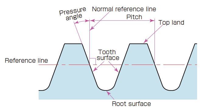
Module (m) , Pressure Angle (α) , and the Number of Teeth, introduced here, are the three basic elements in the composition of a gear. Dimensions of gears are calculated based on these elements.
Tooth Depth and Thickness
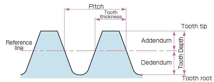
Tooth depth is determined from the size of the module (m). Tooth depth (h) is the distance between tooth tip and the tooth root.

Addendum (ha) is the distance between the reference line and the tooth tip
ha = 1.00 m
Dedendum (hf) is the distance between the reference line and the tooth root.
hf = 1.25 m
Tooth thickness (s) is basically half the value of pitch (p). * Pitch (p) = πm
s = πm / 2
Diameter of Gears (Size)
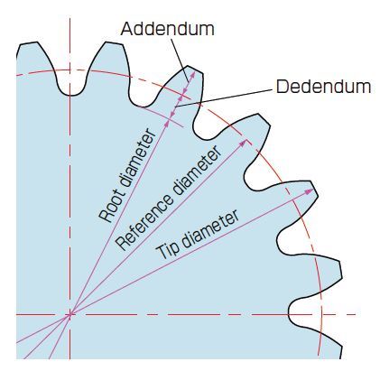
z represents the number of teeth.
Reference diameter (d)
d = zm
Tip Diameter (da)
da = d + 2m
Root Diameter (df)
df = d - 2.5m

Important Definitions
| Tangential Force | Force needed to deliver the linear movement profile | N |
| Torque | This is what the pinion sees and is simply tangential force * arm (radius pinion) | Nm |
| Safety Factor | Recommended at least 2 for horizontal and 3 for vertical drives | |
| Friction Coefficient | How heavy or light does the system run? Widely used value is 0.1 or 0.15 | |
| External Forces | if the system is used to push the products then this force is added to the tangential force |
Points of Attention for the selection of Rack and Pinion
Keep the following in mind
- A pinion of about 20 or 23 teeth is mathematically optimum in terms of tangential force and system backlash. But there’s no hard and fast rule that you need to consider 20 or 23 teeth always, it entirely depends with respect to your application.
A smaller pinion can transmit lower torques and has a higher wear.
With the table below you can perform the calculations
| Application | Unit |
|---|---|
| Total Weight load | m |
| Speed | v |
| Time Acceleration | ta |
| Gravity | g |
| Friction Coefficient | μ |
| Pitch Circle Pinion | d |
| Other Forces | F |
| Safety Factor | SB |
Important Formulas
| Tangential Force | FN | FN = M * g * μ + M * a + F | N |
| Torque | TN | TN = (FN * d)/2000 | Nm |
| Design Torque | TNV | TNV = TN * SB | Nm |
| Max Speed Pinion | NV | NV = (v * 19100)/ d | rpm |
Rack and pinion is often trial and error
For rack and pinion the minimum number of teeth is given by
\(t_{min} \ge \frac{2}{sin^2 \phi}\) where \(\phi = {Pressure\ Angle}\)
Generally 20o is often taken as the pressure angle for involute gears.
Significance of Pressure Angle
- Increasing the pressure angle
- improves tooth strength
- Results in a smaller base circle so more portion of tooth becomes involute thus can eliminate interference
- Will improve power transmission but at the same time will increase gear wear and meshing noise
- Decreasing the Pressure Angle
- Will require more teeth on the pinion to avoid undercutting
- Will decrease power transmission capacity but will improve gear meshing properties like reduced noise
References
- Sciencing - Rack and Pinion: Gear Ratio
- Apex Dynamics - Calculating rack and pinion, how do you do that?
- Linear Motion Tips - How to size a rack and pinion drive
- Testbook.com - Min number of teeth
- Testbook.com - Value of Pressure Angle generally used
- KHK Gear - Basic Gear Terminology and Calculation